
TL;DR
A calcium reactor circulates aquarium water through calcium-carbonate media inside a sealed chamber. Controlled CO2 lowers the chamber pH, the acidic water dissolves media, and a measured stream of enriched effluent returns to the sump.
The reactor does not simply “dose calcium.” Dissolving calcium carbonate releases calcium and bicarbonate alkalinity together. Output is controlled by both effluent flow and how concentrated that effluent becomes. The display tank’s alkalinity trend is the main feedback signal because it moves faster and is easier to measure precisely than calcium.
The chemistry inside the chamber
When CO2 dissolves in water, part of it forms carbonic acid and lowers pH. The lower-pH water can dissolve calcium carbonate media that would remain mostly solid at normal reef-tank pH.
The useful net reaction is calcium carbonate plus carbon dioxide plus water producing calcium ions and two bicarbonate ions. In reef terms, the effluent carries calcium and alkalinity in the same fundamental proportion that calcium-carbonate skeleton formation consumes them.
That does not mean every bag of media is chemically identical. Natural coral skeleton, mined aragonite, and manufactured media can contain different minor elements and dissolve at different rates. Magnesium-rich additions may contribute magnesium, but the amount depends on media composition, operating pH, and dissolution behavior. Treat the label as a claim to verify, not a promise that magnesium will manage itself.
The complete flow path
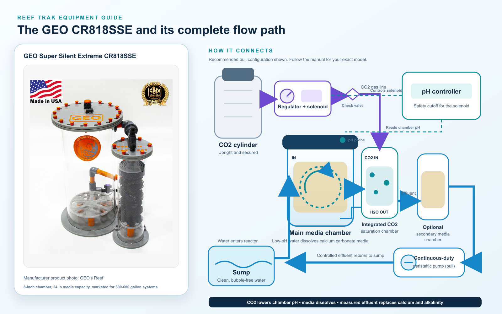
The diagram below uses the GEO Super Silent Extreme CR818SSE because I run an 818 myself. It is a large unit with an 8-inch reaction chamber and 24-pound media capacity, and GEO currently markets it for 300 to 600 gallon systems. Color and finish options vary, but the functional connections are the important part.
In GEO’s recommended pull arrangement, clean sump water enters the main chamber. The recirculation pump keeps water moving through the media and the integrated CO2 saturation chamber. CO2 travels from a secured cylinder through the regulator, solenoid, and check valve to the CO2 input. Enriched water leaves the H2O OUT port, passes through an optional secondary media chamber if installed, then a continuous-duty peristaltic pump pulls the controlled effluent back to the sump.
Classic reactor, SSE chamber, and secondary chamber are not the same thing
A traditional Classic-style reactor injects CO2 into the recirculating water and commonly uses an external bubble counter. GEO’s Super Silent Extreme design adds an integrated CO2 saturation chamber so most of the gas dissolves before reaching the main media chamber and recirculation pump.
That integrated CO2 chamber is not an optional second media chamber. A true secondary media chamber sits after the reactor’s H2O OUT line. Effluent passes through more calcium-carbonate media before the flow-control pump or needle valve returns it to the sump.
The external plumbing concept remains the same across both designs: aquarium water in, controlled CO2 in, internal recirculation, and measured effluent out. The port names and exact path matter, so use the manual for the model in front of you instead of copying a photograph of a different generation.
The two controls that determine reactor output
Reactor output has two parts. Effluent flow determines how much treated water returns to the aquarium. Effluent concentration describes how much alkalinity and calcium that water carries. A simplified way to think about net alkalinity delivery is effluent flow multiplied by the difference between effluent alkalinity and aquarium alkalinity.
Lower chamber pH generally dissolves more media and raises effluent concentration. Slower flow increases contact time and can also raise concentration, but returns fewer milliliters per minute. Faster flow returns more water but may reduce the concentration of each milliliter. This is why bubble count alone cannot describe reactor output.
The chamber pH is not the aquarium target. It is an operating value chosen for the media and reactor. GEO’s current manual lists example starting points of about 6.6, 6.5, or 6.4 for three common media grades and about 40 mL per minute for the CR818. Those are manufacturer starting points, not universal numbers for every medium, probe, tank, or reactor.
Alkalinity demand is the feedback signal
Before starting the reactor, bring aquarium alkalinity, calcium, and magnesium to their intended values with a one-time correction. A reactor is best at replacing ongoing consumption. It is a slow and awkward tool for repairing a tank that begins far outside the target range.
Then test display alkalinity at a consistent time. If alkalinity falls across several readings, the reactor is replacing less than the reef consumes. If alkalinity rises, it is replacing more. Calcium usually changes too slowly and within too much test noise to be the primary tuning signal.
GEO recommends testing both display and effluent alkalinity every 12 to 24 hours while dialing in, recording effluent pH, and changing only one setting before allowing the system to settle. That discipline matters. Simultaneously changing bubble rate, setpoint, and effluent flow may move alkalinity, but it will hide which control caused the change.
A practical startup and tuning sequence
The exact assembly steps belong to the manufacturer manual, but the tuning logic is transferable. Establish the baseline first, start conservatively, collect repeatable measurements, and let demand set the final output.
- Secure the CO2 cylinder upright and install the correct regulator, solenoid, tubing, and check valve
- Leak-test the reactor and tubing with water before adding media or CO2
- Calibrate the pH probe, install it without creating an air leak, and confirm port labels
- Bring display alkalinity, calcium, and magnesium to the desired starting values
- Start from the reactor and media manufacturer’s conservative pH and effluent guidance
- Measure actual effluent flow instead of trusting a dial or nominal pump setting
- Record display alkalinity, effluent alkalinity, chamber pH, and flow at consistent times
- Change one variable, wait 12 to 24 hours, then measure again
Once chamber pH is stable for the chosen media, many systems are easiest to tune by changing the peristaltic pump’s effluent rate. The pH controller then acts mainly as a high-confidence gas cutoff rather than cycling the solenoid constantly.
Why a calcium reactor can lower display pH
Reactor effluent is below normal aquarium pH and can carry dissolved CO2 that has not been consumed by media dissolution. When that effluent enters the system, some of the extra CO2 reaches the display and shifts pH downward until gas exchange removes it.
The size of that effect depends on total reactor output, gas efficiency, room CO2, aeration, skimming, refugium timing, and where the effluent enters. Do not chase the display pH by forcing chamber pH too high if the media stops dissolving. Improve gas exchange, correct excess gas injection, and evaluate the complete system.
A second media chamber can consume some remaining acidity and raise effluent pH modestly while extracting additional alkalinity from the gas already used. It cannot compensate for a badly overfed CO2 line, a poorly ventilated room, or a reactor producing far more effluent than the tank needs.
What the pH controller should do
A pH controller reads the probe in the reactor and controls the regulator solenoid. If chamber pH falls below the safety point, it closes the gas. If pH rises, it can allow gas again.
The controller should not be asked to correct an aggressive bubble rate by switching the solenoid every few minutes. Set the regulator and needle control for a slow, deliberate gas feed, then use the controller as a guardrail. GEO’s manual makes the same distinction: the better the mechanical gas setting, the less the solenoid has to cycle.
Probe accuracy matters because a drifting probe changes the apparent chemistry of the whole reactor. Calibrate it on schedule, keep the probe wet as required, inspect the fitting for leaks, and replace an unreliable probe before compensating with more CO2.
Common failure modes
Most calcium-reactor trouble is easier to understand when it is separated into flow, gas, media, and measurement problems.
- Clogged effluent tubing or a needle valve changes output even when pH looks stable
- An air leak on the pull side makes a peristaltic pump lose prime or draw gas
- A failed check valve lets water migrate toward the regulator
- Channeling, compacted fines, or exhausted media reduces useful contact
- A miscalibrated pH probe drives the controller toward the wrong chamber condition
- A wide-open CO2 rate makes the controller cycle instead of controlling a stable process
- Changing several variables at once makes the next alkalinity reading impossible to interpret
- Using the reactor to raise already-low alkalinity quickly overshoots after the delayed response arrives
Calcium reactor, two-part, kalkwasser, or a hybrid
The best method depends on demand, tank size, space, desired pH effect, and how much equipment you want to manage. None is automatically more advanced or more stable. Stability comes from matching the method to consumption and measuring the response.
A practical comparison of the four common supplementation approaches.
| Method | Best suited for | Main strength | Main drawback |
|---|---|---|---|
| Two-part | Low to medium demand, or owners who want direct independent adjustments | Easy to understand, automate, and correct | Ongoing chemical cost and salinity creep at high demand |
| Kalkwasser | Low to moderate demand with predictable evaporation | Adds balanced calcium and alkalinity while supporting pH | Limited by evaporation and high-pH dosing risk |
| Calcium reactor | Moderate to very high demand, especially large SPS systems | Continuous balanced output with low recurring media cost | More equipment, slower tuning, and possible display-pH suppression |
| Hybrid | High-demand systems that also need pH support | Reactor capacity plus kalkwasser’s pH benefit | More equipment and more interacting variables to monitor |
Who should use a calcium reactor
A reactor makes the most sense when daily calcium and alkalinity demand is high enough that mixing, dosing, and buying two-part has become a recurring burden. Large SPS systems, mature mixed reefs, coral farms, and commercial holding systems are the obvious candidates.
It is less attractive when demand is small, cabinet space is tight, the owner does not want a compressed-gas system, or alkalinity testing is inconsistent. A reactor can be extremely steady after it is tuned. It is not self-managing. Flow, probe calibration, media level, pump condition, and display alkalinity still need attention.
The CR818 is the example here because it is a real large-system reactor and one I use. The chemistry is the same in a smaller unit. Scale changes capacity and starting flow, not the logic of CO2, media dissolution, measured effluent, and alkalinity demand.
The bottom line
A calcium reactor is a controlled carbonate-dissolution system. CO2 lowers the chamber pH. The media releases calcium and alkalinity. Effluent flow determines how much enriched water returns to the tank. The alkalinity trend shows whether that output matches coral consumption.
Once those four ideas are separated, the reactor stops looking mysterious. Use the manufacturer’s plumbing and starting guidance, tune one variable at a time, treat the pH controller as a safety layer, and let measured alkalinity demand decide the final setting.